Our wind turbines and solar panels are not connected to the national grid, so we have to strictly control our energy storage and usage.
There is nothing economically viable currently on the market regarding battery management systems, so we have constructed a multi-battery LVD (low voltage disconnect) system. Here’s how it works…
The wind turbines and the solar panels feed into 3 charge controllers. These controllers can handle 45A each. Our circuit system is 48V, and the chargers charge the system up to 56.8V. Once the batteries are charged, the chargers drop to "float" at 54V.
The OzInverter is constantly running 24/7, as it draws only 45watts, where are previous UPS Inverter would use 150W to 250w just on standby. ... it is very important for the longevity of our 40 batteries that they stay well above 40V. - We have 10 banks of 4 batteries @ 12V in series =>48V, giving us 1300 AmpH.
If a 12V battery drops below 12V, the battery life is much shortened. Looking at other people’s systems on the renewable energy forums, it seems that 12.3V (x4=49.2) is a good “safe” LVD voltage at which to shut down the inverter so that it does not drain the batteries. Hence they have a longer life. - A good thing, since batteries can be the most expensive component of a domestic power station, so it is worth keeping them in good health!
Curiously, in each bank of 4 batteries, one of them will always drop lower than the others, but … each time the batteries are recharged and power re-drawn, it is usually a different battery that goes down! - Anyone who can come up with a good reason for this, we invite you to post on our blog!
So ... our new circuit will monitor every battery with a small box of tricks, and also contains a minicomputer that will examine every battery’s voltage, every minute. This info is stored on a data chip and analysed on the PC to see which offending batteries need special care and attention.
Our circuit will therefore check every battery when the power is being drawn, and when one battery gets to 12.2V, it will shut down the inverter i.e. turn it off, to prevent any of the batteries becoming so sick that they can no longer hold a charge. It also allows the inverter fan to continue working whilst the system cools down properly.
We will start posting test results shortly, and will happily share more details if you need support for a similar project!
With thanks to Eric Ward for arranging the circuit to run with PIC programming, without which this system would not function!
Translate This Page
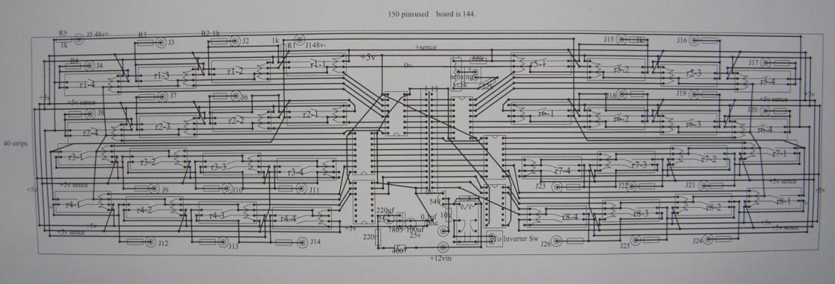
1. Circuit diagram
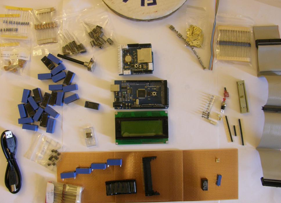
2. Circuit components
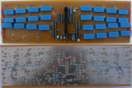
3. Circuit
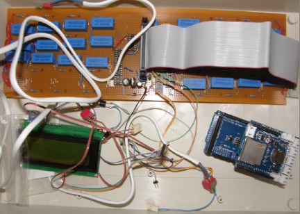
4. Completed system - ready to test!
© 2025 Le Vivray Sally Woods-Bryan & Leslie Bryan Microengineering